Rebound models
Impact detection algorithm
A first version of the point cloud impact detection algorithm was presented at the 12th International Symposium on Landslides - ISL 2016:
This old version was dependent on the surface orientation of the terrain. This made it rather sensitive to noise and artifacts present in the point clouds used, and produced different results depending on the radius and the method used to determine the orientation of the terrain. Also, the rebound model that had been combined with the algorithm to test it was then based on the equations of the Thesis of Wyllie C. Duncan (2014), unlike the experimental rebound models of the current version of stnParabel.
The description of the new version of the impact-detection algorithm (2021) as well as the description of some existing rebound models integrated into stnParabel for validation purposes are available in open access in:

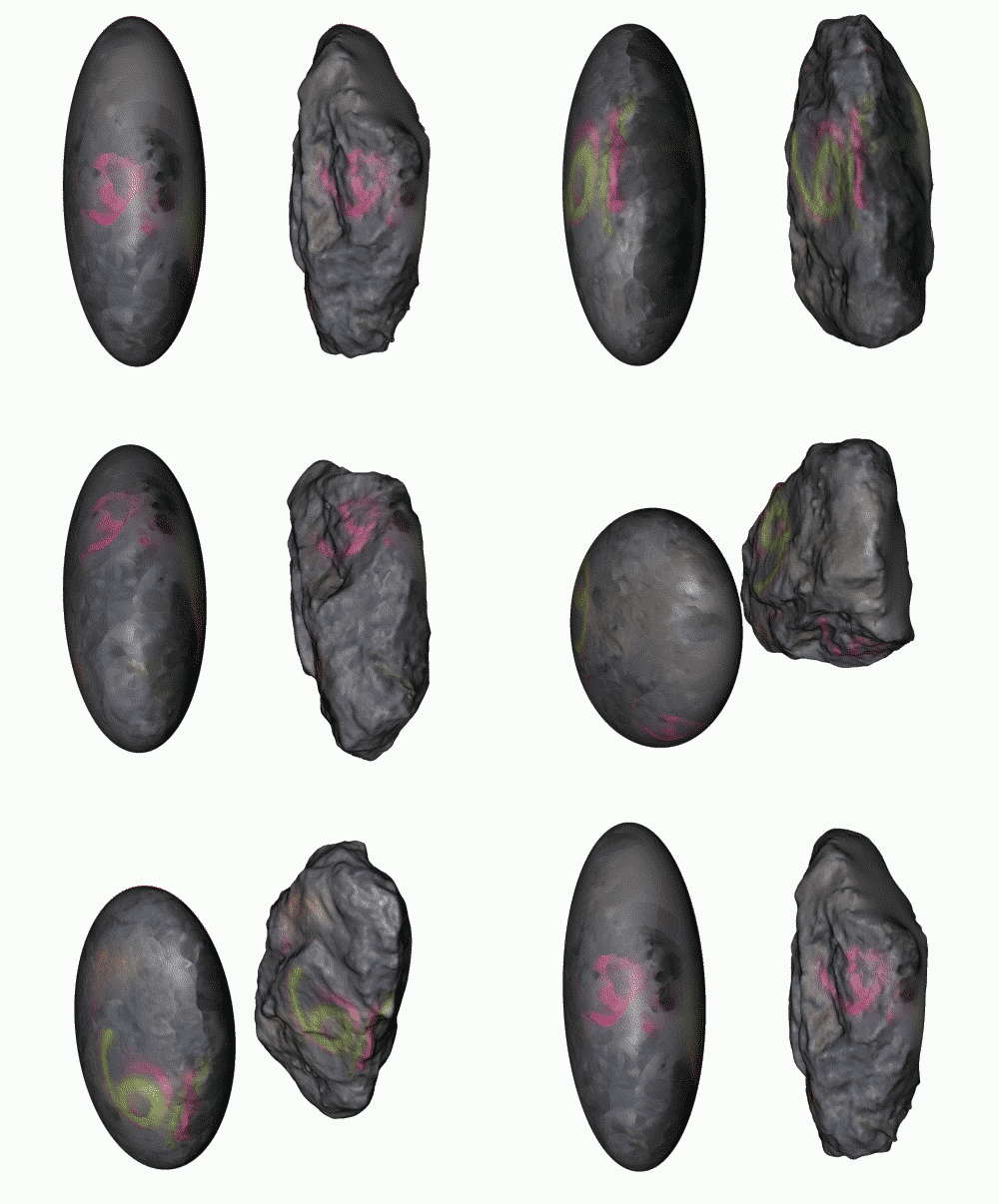
Representation of the shape of the rocks simplified with rotation around the axis d3.
The current algorithm does not use the terrain surface orientations determined in the "Terrain" section. These are only used for the definition of multiple sources according to slope thresholds or kinematic tests, and for the optional addition of surface roughness and materials according to slope thresholds. Its operation is relatively simple, which allows a rather fast simulation of rockfall by considering a high level of detail of the terrain. The shape of the rocks is simplified to that of a sphere of diameter d1 for the search for contacts with the ground, Trees or other elements, and uses the moment of inertia based on an ellipsoid of diameters d1-d2-d3 rotating around the axis d3 during rebounds.

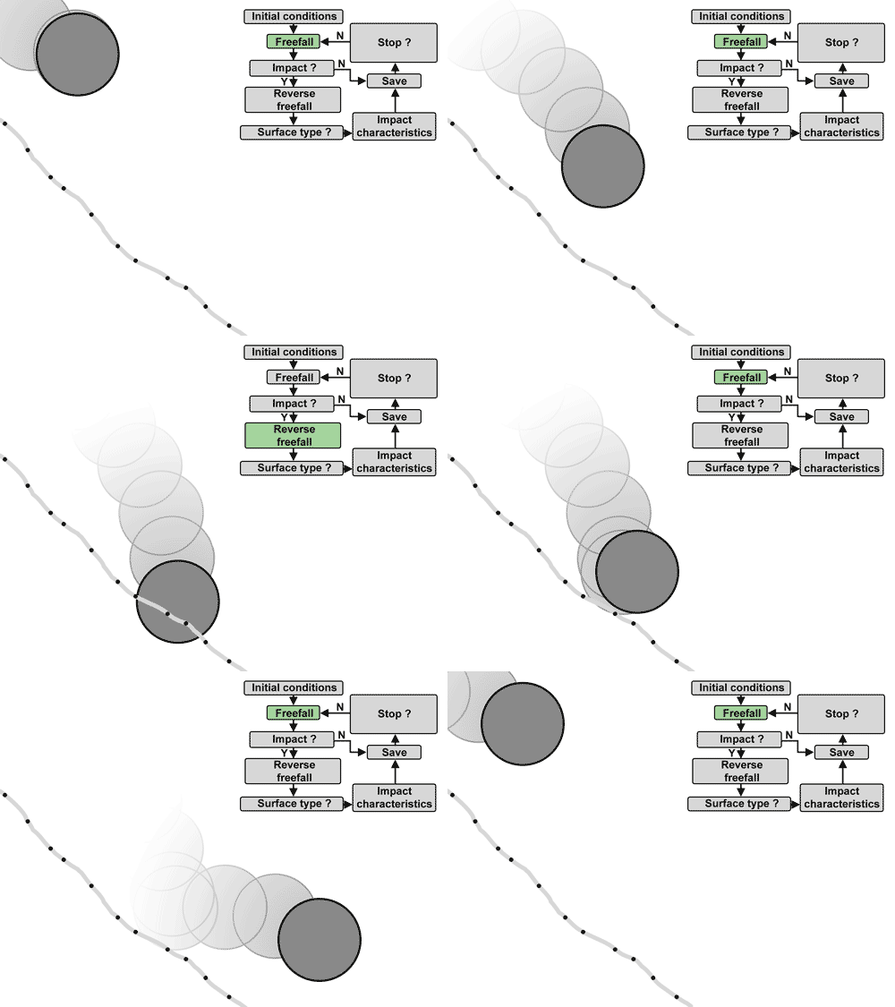
Simplified operation of the impact detection algorithm.
The algorithm consists in moving the rock in free fall with air resistance. The drag is determined using Rayleigh's law with an air density of 1.2 kg/m3, a reference impacting surface seen from the front in the form of an ellipse with diameters d1-d3 and a coefficient of drag of 0.9. Then check if any points are impacted after each distance traveled from 70 to 85% of the maximum diameter d1. If this is the case, several options are possible:
If a fence is impacted, the rock is stopped and the trajectory is saved;
If an infrastructure is impacted, the information of the first impact of this type per trajectory is recorded and the free fall continues;
If the ground or a trunk is impacted, the previous free fall is reversed (the time is negative) until the precise position of impact is found tangent to the points, or tangent to the surface of the trunks of conical trees. For the rebound against the tree stem, the rebound model is then applied (see subsection “Rebound model against the tree stems).
If there is an impact against the terrain, the points of the terrain around the impacted point are then isolated within a radius of ½ d1 and a plane is adjusted to them. If the plane corresponds well to the points (RMS < 0.04 * d1), and therefore that the ground is locally smooth, the rock is moved in reverse free fall until it is tangent to the plane and the terrain orientation perceived by the rock is given by that of the plane. If not, the orientation of the perceived ground is given by the normalized vector starting from the impacted point and pointing towards the center of mass of the rock. The rebound model is then applied for the rebound (see subsection “Rebound models against the ground").
Rebound model against tree stems
The rebound model against the tree stems uses the equations used in Rockyfor3D v5.2, based mainly on the work of Luuc Dorren and Frédérique Berger and tested in the thesis of Martin Jonsson (2007) and is described in detail in:
The lateral deviation that occurs after an impact against a trunk is based on the probabilistic deviations (θRF3D) used in Rockyfor3D v5.2. It is however adjusted downward arbitrarily according to the change in velocity (RV_tree = Vout/Vin) caused by the impact against the trunk as follows: θstnParabel = θRF3D*(1-RV_tree3). This modification ensures that high energy impacts against small trunks, where the rock loses little energy, can only be slightly deflected (e.g. θstnParabel = ~ 99% of θRF3D for an RV_tree 0.2, ~ 88% for 0.5, ~ 27% for 0.9 and ~ 3% for 0.99).
Rebound model against barriers
stnParabel v.June 2021 does not consider the deformation of fences and walls or their ability to resist impact. The rebound model against the ground is used for the walls. Also, blocks are stopped as soon as they touch the fence, whether their center of mass is inside or beyond the limits of the fence, and regardless of the energy at impact. It may therefore be necessary to slightly reduce the height of the fences by half the diameter (½ d1) of the rocks for the simulations.
Rebound model against the ground
The fragmentation of rocks is not currently taken into account during impacts against the ground. Different existing rebound models were tested, combined with the original point cloud impact-detection algorithm of stnParabel. Some of these existing models are based on Pfeiffer and Bowen (1989), and therefore on coefficients of restitution (COR) functions of Rt, Rn, Rg10, Rg20, Rg70, soiltype, angle of impact, etc., to determine the instantaneous energy loss that occurs on impacts (contact time is neglected). The choice of the different damping factors making it possible to determine the CORs can however introduce a large bias, because these damping factors are often difficult to measure in the field and specific to each software. Some of these rebound models can still be used in stnParabel.
Other rebound models take into account a duration of contact during which the velocity of the rock changes according to the various forces due to the contact. The rock is generally considered to be a rigid body. Impacted surfaces generally have a certain tolerance to denting in order to avoid rigid-rigid contact. Such a contact otherwise would generate infinite forces during impacts and zero contact times, complicating the application of the friction forces. Friction forces are often defined according to Coulomb / Mohr-Coulomb. The Rolling friction rebound model and experimental Scarring model developed for stnParabel use this type of approach to determine the evolution of the rotation and translation velocities of the rocks. They then use empirical relationships based on rockfall experiments to apply the lateral and vertical deviations.
The "lateral" deviations are applied by a rotation around an axis passing through the center of mass of the rock and perpendicular to the perceived terrain. The "vertical" deviations are applied by a rotation around an axis passing through the center of mass of the rock and perpendicular to the preceding axis. They are defined in such a way as to best satisfy empirical relationships established after 3D measurement of over 400 real impacts, ranging from a few kilojoules to a few hundreds of megajoules. The shape and inertia of the studied rocks was measured precisely from 3D models and onfield wheigting or sampling weighing for the density of the two blocks above 180m3. These relations use among others the changes of velocities in [X, Y, Z] and of rotation, the elongation of the rocks according to the ratio d2/d1, the flattening of the rock according to the d3/d1 ratio, the incident angle with the perceived terrain, the difference in orientation of the terrain relative to the direction of the rock before impact, etc.
The two new models for determining velocity changes are briefly described in the following subsections for an overview pending publication of the detailed description of their operation. Both use the mass entered through the stnParabel interface and the inertia of the block simplified to an ellipsoid rotating around the d3 axis to determine the velocity changes.
The first model (Rolling friction model) is the simpler to use of the two, since it does not require a definition of the terrain materials. At the time of this writing, the author has tested it for 8 different sites affected by past events and obtains trajectories and runouts similar to those observed for 7 of the 8 sites. However, the model struggles to reproduce one of the two stopping positions (the one at the longest runout) for the event that affected Holaviki described in:
Domaas, U. (Norwegian G. I. (1995). Natural rockfalls - Descriptions and calculations.
The rockfalls reach impressive speeds for this site because of the high wall (they mostly exceed 50 m/s), and the materials at the bottom of the slope have surely a low resistance, because of their water content probably high. The second model can then be used for these particular cases in order to have more control over the interaction between the block and the surface materials.
Rolling friction model
This model, original to stnParabel, assumes a certain scarring of the terrain by the impacting rock, without however calculating it in detail. The model is described in detail in:
The acceleration in the direction of the normal to the ground (αN) is simplified to a constant value. This makes it possible to obtain the force normal to the ground which is applied over a time interval (δT) during which the rock sinks into the ground and leaves it. This contact time is defined by the time (δT_decel) necessary for the rock to have a velocity normal to the ground (VN) zero, to which is added a short period of time (δT_accel) necessary for this velocity to allow it to move away from the terrain again.
During this time δT or until the rotational velocity (VRot) of the rock synchronizes with its translational velocity (VT), a frictional force is applied using the force normal to the ground as a function of Mohr-Coulomb, affecting VT and VRot. The direction of this force is parallel to the ground and depends on the slipping or skidding of the rock. If the rotation is synchronized, a simple rolling resistance is applied until the end of the contact with a rolling resistance coefficient (bRot) function of VT_in and ½ d1. An arbitrary limit prevents the rock from decelerating more than 90% of its initial speed on impact.
The material properties are fixed at a φ' of 28° and at a cohesion of 30 kPa for this model (since the shear under the rock does not occur only at the rock-soil interface but also slightly through the ground). These values were chosen in order to obtain the best R2 when comparing the model to the impact database (over 400 impacts, from a few kilojoules to a few hundred megajoules). This comparison was automated in order to test thousands of combinations of parameters and to choose those allowing the best reproduction of the restored velocities (tangential, rotation, angles of deviation, etc.).
Scarring model
This experimental model, original to stnParabel, calculates the scarring of the rock in the ground as a function of the bearing capacity of the soil for the properties of the materials defined locally with respect to the slope thresholds. The dynamic lift created by the projection of the soil at the front of the rock is also combined there until the rock reaches its maximum sag (when VN changes sign). This dynamic lift then acts alone on the rock until the end of contact. Cohesion is only applied for the bearing capacity of the soil, and not on the dynamic portion of the soil projected forward or on the friction between the rock and the soil.