Surface roughness and materials
Included surface roughnesses
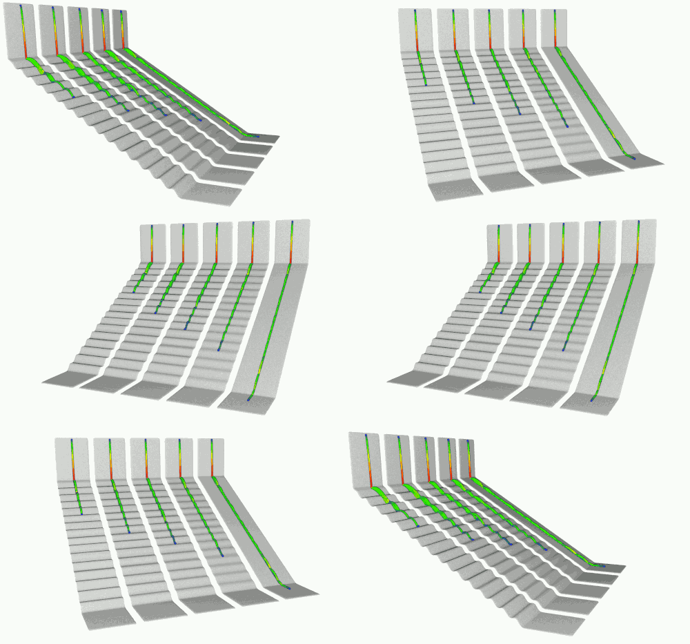
Adding roughness is only necessary if the terrain used does not have a high level of detail. The rebound models are sensitive to the angle of the impacted terrain perceived as a function of the size of the simulated rocks. If the terrain is of poor quality, it may not have the roughness that would normally be impacted by small rocks and slow them down. This risks creating greater travel distances for these small rocks and reducing lateral deviation. It is then possible to add the missing level of detail by assigning the roughness to the terrain from detailed terrain samples.

The level of detail of the terrain perceived in relation to the size of the rocks has an important influence on the propagation.
The tool then simulates nearly 20,000,000 impacts (contact detection only, without the calculation for rebound) against the terrain sample for the defined rock size. This makes it possible to evaluate the variation in orientation of the terrain which should be perceived by the rock. This is then added to the poorly detailed terrain when the impacts are detected during the simulations. For more details on the roughness included, see:
Adjusting the scale
These roughness can be loaded into CloudCompare for visualization (see section "Terrain / Other sources / Elevation grid (raster)". Their scale can be modified there in order to generate new custom roughness from existing ones with the CloudCompare's Multiply / Scale tool. These new roughness should be exported as an elevation grid (raster), ideally using the same number of rows and columns as the loaded roughness (approximately 500x500 to 1500x1500), the Rasterize tool can be used to do this with the cell height option set to average height .
Custom surface roughnesses
New roughness can also be created for the project, for example from detailed SfM or mobile terrestrial LiDAR data. To do this, it is necessary to locally cut the sector to the desired roughness while keeping a little margin around it. It is also necessary to cut out the poorly detailed terrain for the same sector, and to orient them by rotation around the vertical axis (Z) (e.g. with the Interactive Transformation Tool or Apply Transformation tools ) so that their slopes face south ( slope aspect or dip direction of 180°).
Then the point density of the poorly detailed terrain segment can be locally increased to a density similar to that of the detailed terrain using the same technique as that for Hole filling during terrain preparation (see section "Terrain / Hole filling" ). The two terrain segments can then be cut in the form of a tile (eg with the Interactive Segmentation Tool and the Rectangle edition mode option ).
It only remains to generate the elevation model of the difference between the two grids ( DEM of Difference - DoD ). This could be done in GIS software with a raster calculator, but it is also possible to do it in CloudCompare. The CloudCompare 2.5D Volume tool can be used from the two terrain segments as point clouds to calculate the difference between the two layers. Choose the interpolation options for empty cells, and use the average elevation to estimate the height of the cells. You have to choose a cell size (step) allowing to obtain a number of rows and columns close to 1000x1000. The grid of the difference can be exported to the CloudCompare working environment and cleaned up manually if it has extreme values. It only remains to convert it to a raster, using the same cell size, to be used as roughness in stnParabel (see the Rasterize tool).
Terrain materials
Regarding materials, it is not necessary to define them if the "rolling friction model" is used. If no material is defined or if the "rolling friction model" is used, a φ' of 28° and a cohesion of 30 kPa are assigned by default. The density of the soil is fixed at 2000 kg/m3. The properties of impacted soils can be defined when adding surface roughness by slope class. If no roughness should be added, it is possible to use the included terrain roughness named "dod_no_roughness.tif".
The choice of properties must be made considering these aspects:
The state of deterioration/weathering of the materials on the surface (from the surface to slightly beyond the estimated depth of penetration of the rocks);
The degree of saturation of materials on the surface and their permeability, because the impacts correspond to sudden loads. This can cause a significant drop in the resistance of the medium if the water pore pressure takes up all the load;
The properties of the environment in relation to the size of the rock: for a small rock on a scree slope composed of large blocks, the properties of the slope should be similar to those of the individual blocks making up the slope.